Description
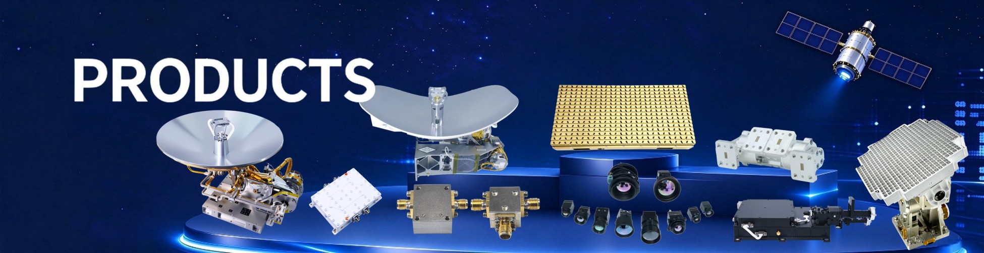
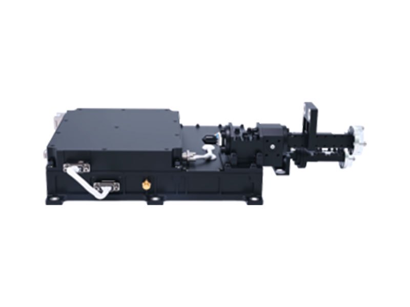
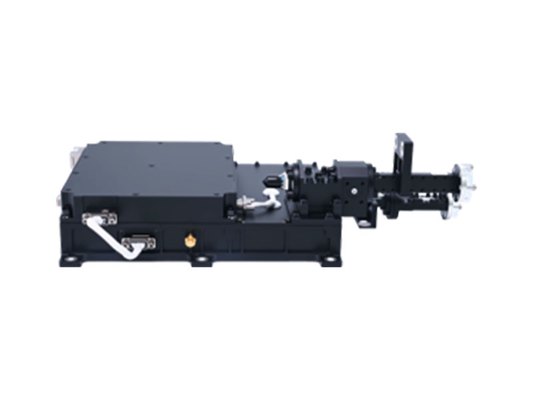
Receive a V-band uplink signal (including multiple service signals + 1 accompanying telecommand signal) from the antenna and perform low-noise amplification. Receive signals, amplify the power to ≥ 38.5 dBm, and output to the antenna. Internal power distribution and control. Configure power supply according to operational requirements and provide agreed telemetry data. Switching and telemetry functions. The solid-state amplifier includes switch control. Undervoltage protection, overtemperature protection, and output overcurrent protection.
Technical Specifications
Test Item | Performance Indicator | Unit |
Forward Input/Output Signal Frequency | QV-band | GHz |
Reverse Input/Output Signal Frequency | QV-band | GHz |
Forward Input/Output Level | Service Input: -87 to -57 Service Output: -40 to -10 | dBm |
| Telecommand Input: -87 to -57 Telecommand Output: -40 to -10 | dBm |
Reverse Input/Output Level | Single Beam Input: -19±1 Single Beam Output: ≥ 32.5 | dBm
|
| Multi-Beam Input: -13±1 Multi-Beam Output: ≥ 38.5 | dBm
|
| Telemetry Input: -29±1 Telemetry Output: ≥ 22.5 | dBm
|
Reverse EVM | ≤ 7% (4 beams, 12 carriers, 16QAM) | % |
Test Item | Performance Indicator | Unit |
ACPR | ≤ -20 (100MHz integration bandwidth; adjacent channel spacing 100 MHz) | dBc |
Forward In-Band Flatness | ≤ 0.6 (any 240 MHz effective bandwidth); ≤ 2 (47.2~49.2 GHz) | dB |
Reverse In-Band Flatness | ≤ 0.6 @ 37.5~38 GHz | dB |
Forward Out-of-Band Rejection | ≤ -65 @ 37.5~40 GHz | dBc |
Reverse Out-of-Band Rejection | ≤ -52 @ 42.5~43.5 GHz | dBc |